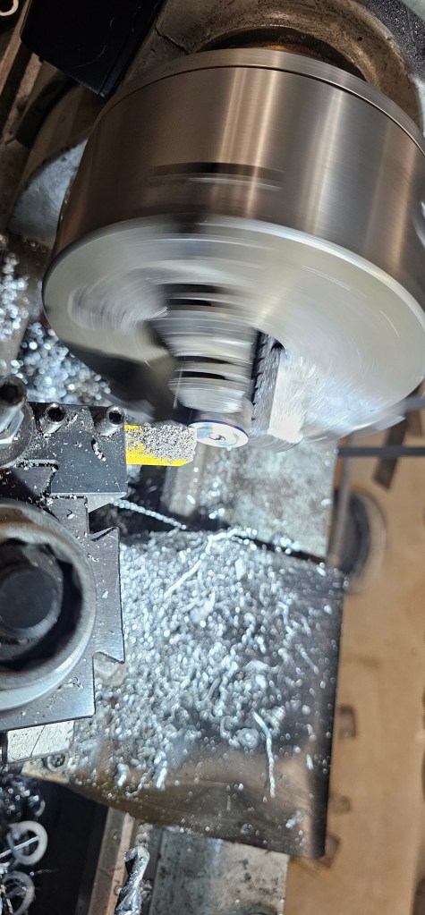
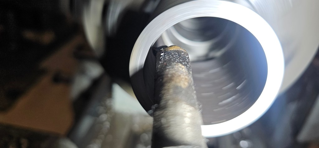
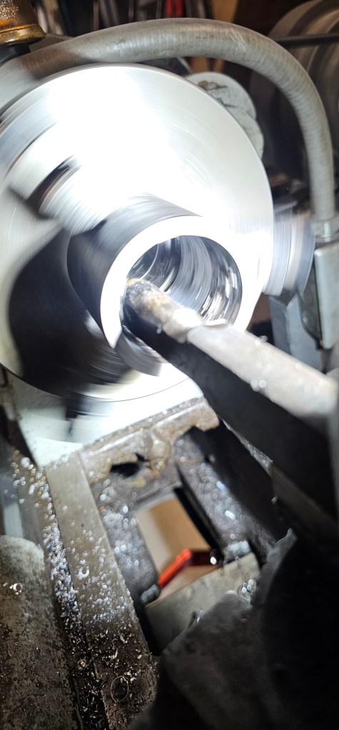
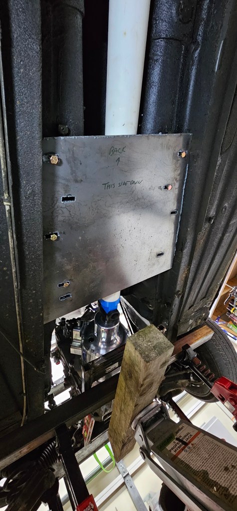
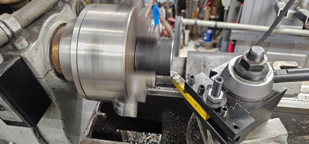
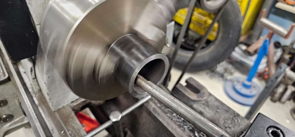
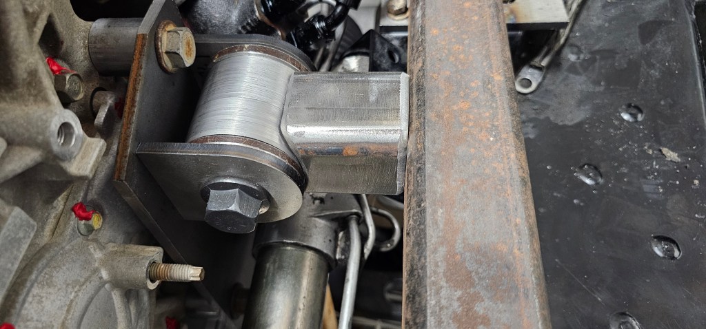
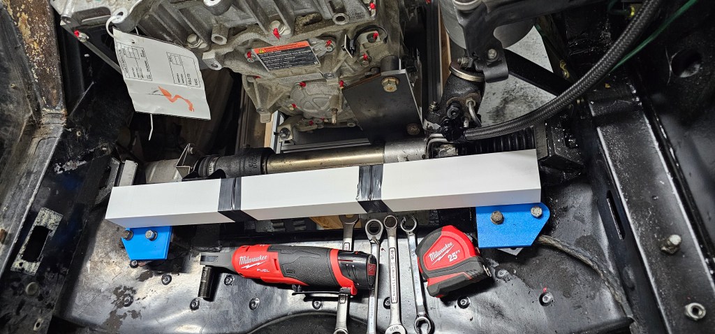
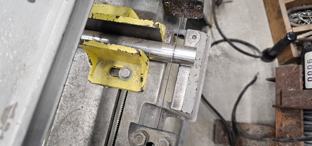
The last two weeks I have worked on fitting the rear mounts for the motor cage. This involved making spacers (twice…erm, oops) for the belly pan plate and boring out a steel tube that will fit over the rubber mounts.
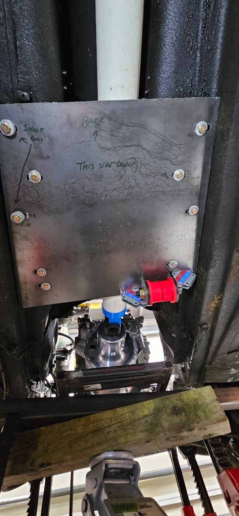
The next step is to weld up the back of the rear mounts, drill and tap some holes for sliders and fit it to the belly pan plate.
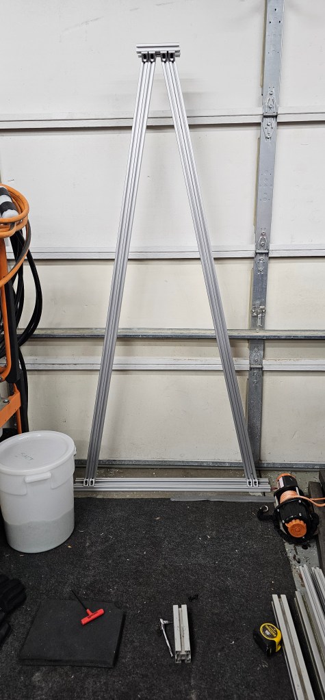
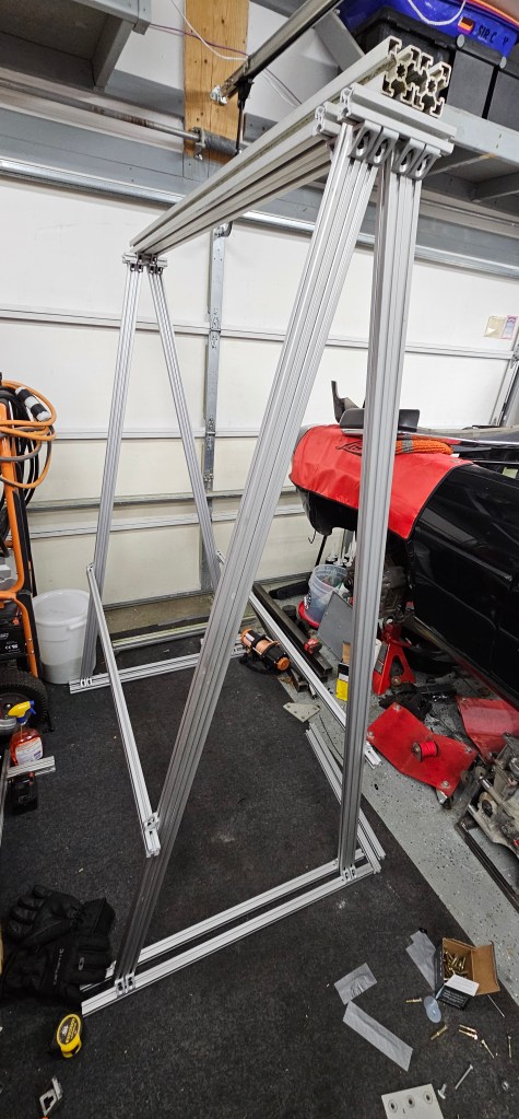
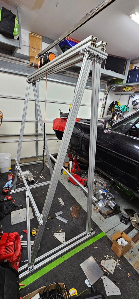
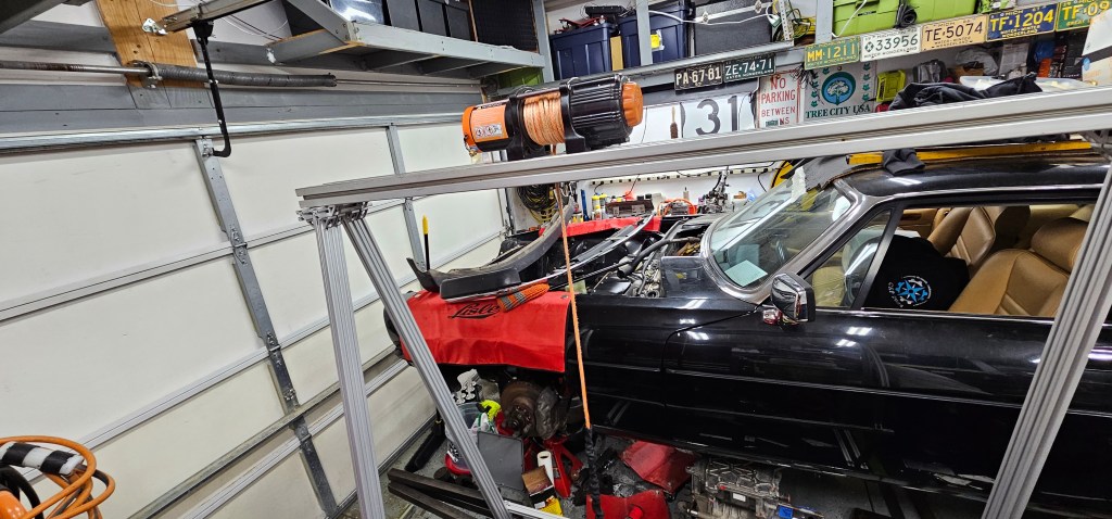
I needed a way to easily get the motor on and off of my floor jack, or in and out of the cradle. Because of limited space and a sloping driveway, a traditional engine hoist/cherry picker wouldn’t work well.
So….I made this thing:
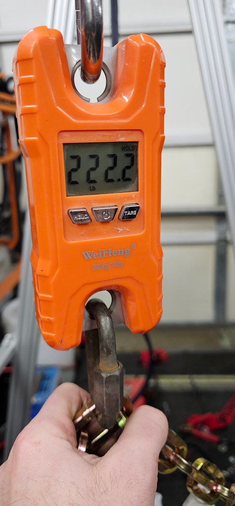
I was happy to see the motor, TorqueBox and cradle all weigh only 222.2lbs – – maybe that’s a lucky number now?
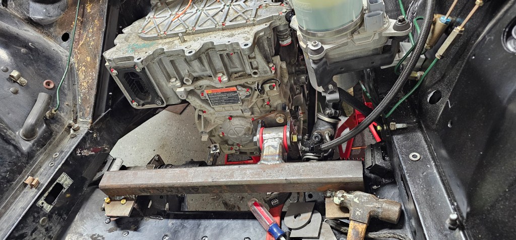
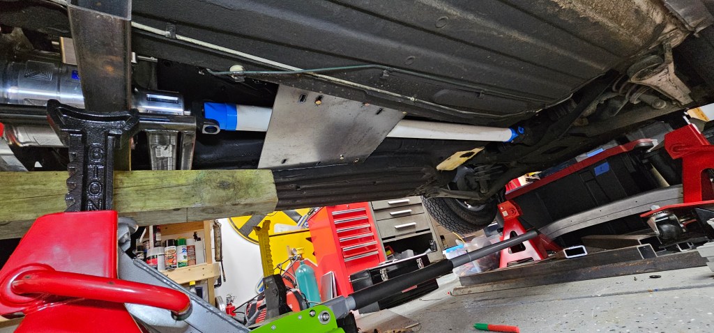
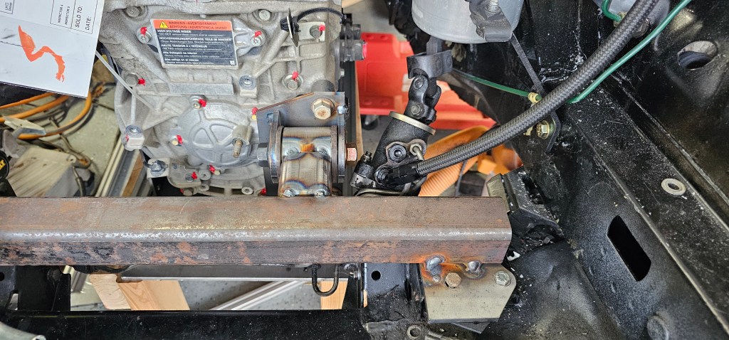
Once I had the motor assembly on the floor jack, I lifted it back into position and connected the front motor mount for the first official time.
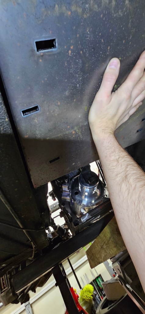
Now the next step is to make spacers for the plate that goes where the transmission was (to clear the driveshaft) and fabricate the trailing arms. The PVC driveshaft placeholder fits exactly as it should.
It’s been nearly nine months since I’ve had the chance to work on the Jag. Just been a busy, busy year.
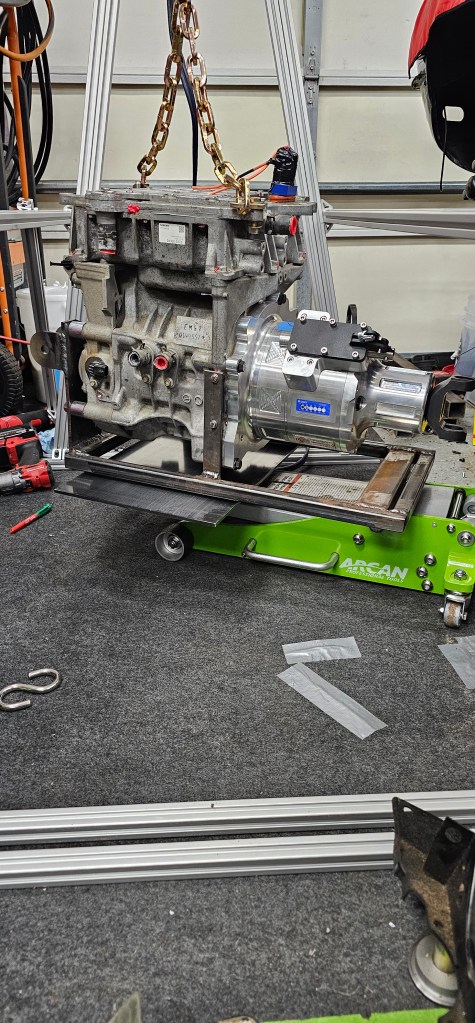
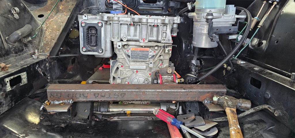
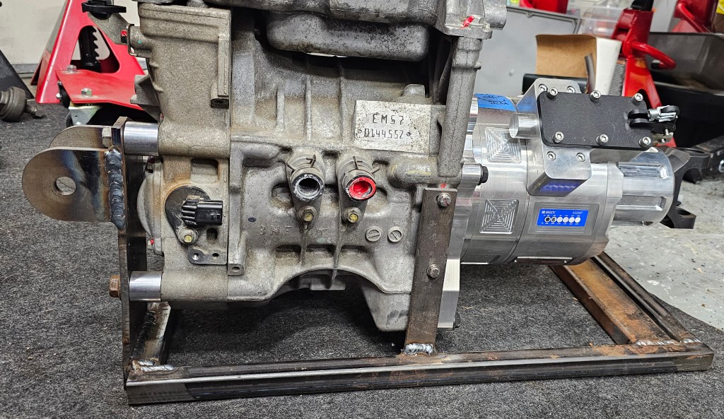
Anyway, where did we leave off? Oh, right, I welded up the motor carrier. So today I went to see if the motor fit in the carrier I welded up back in March. Spoiler: it did!
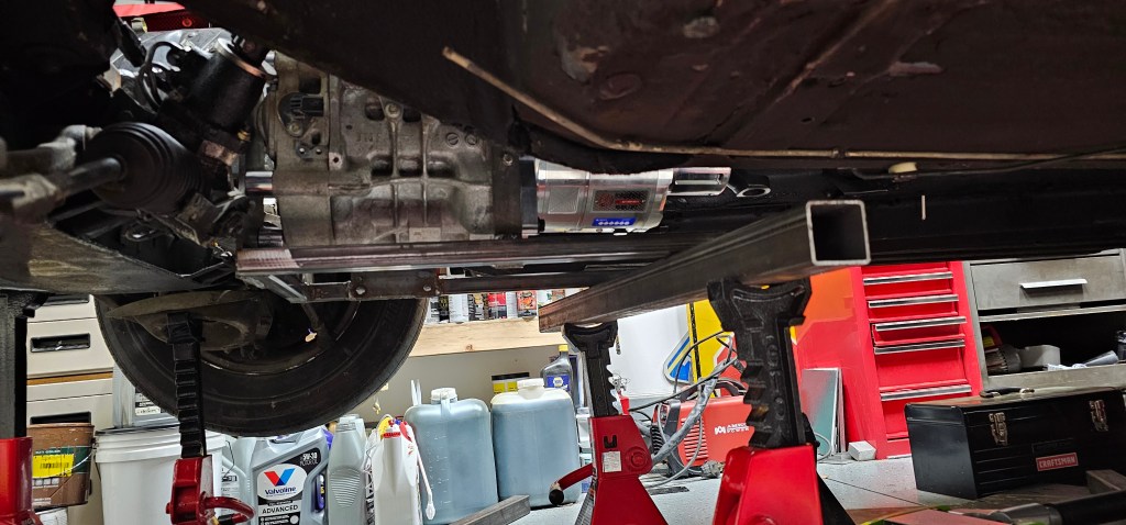
Next step is to get this on a transmission jack, hope it clears under the car with the transmission jack, and put in place to figure out where the rear motor mounts need to go.
After that, make a tailstock support and get a driveshaft made!
Until next time (and I promise it won’t be another 9 months…)
I have all the parts cut, fitted, and tack welded for the front motor mount. Next step is to do the final welds, sandblast and paint. After that I will focus on a plate that needs to span over the driveshaft where the old transmission mount was, motor bucket and rear trailing arms.
This year has certainly started off extra busy and I haven’t had a lot of time since Christmas to work on the Jag.
A few things…
I got a PTC heater and CAN/LIN unit from EV Create (https://www.evcreate.com/volkswagen-air-ptc-heater-control-via-lin-bus/) in early January and an AC evaporator that should fit up to it nicely! I’ll be making a complete air box from scratch with servo-controlled dampers, so be on the look out for that in the future.
I have the start of the front motor mount underway, with some plates I had laser cut at SendCutSend along with a piece of 2″ square stock. I tack welded these and will pull it out of the car to do the final weld. I’m certainly not a welder, so this project will help me hone those skills.
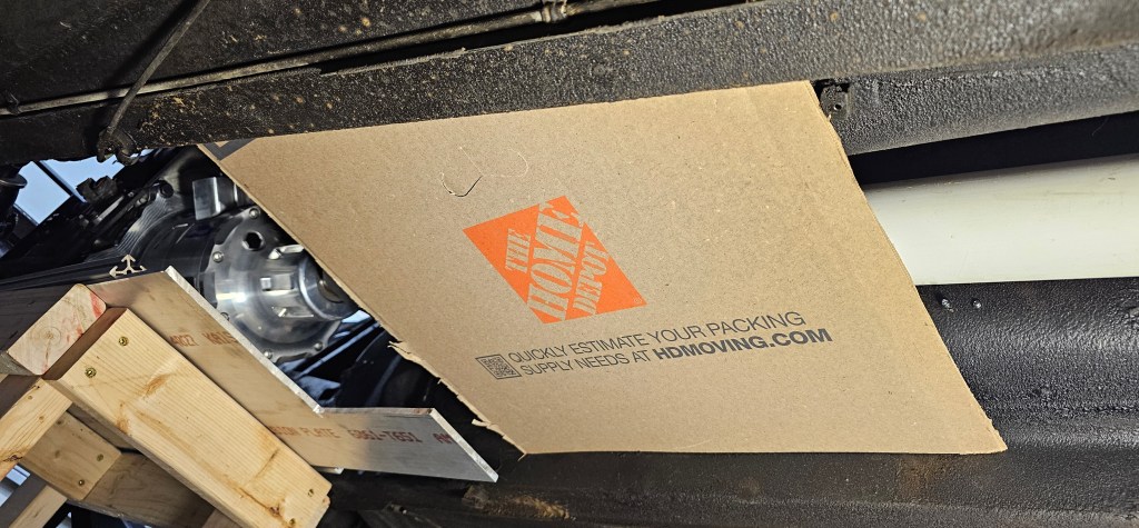
Lastly I started making a cardboard template to draft what the bottom plate of the car will look like. This plate will mount under the driveshaft where the original transmission support mounted. This will then have two trailing arms that will support the back of the motor/gearbox “bucket”
HOPEFULLY by the end of March I’ll have the motor mounted in place and can start working on getting a proper driveline built and balanced.
My holiday break officially comes to a close, but I made a LOT of progress. Hopefully I’ll have some time over the next few months to get this motor buttoned down.
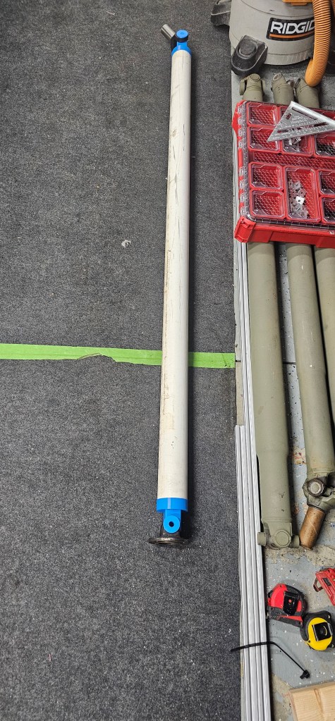
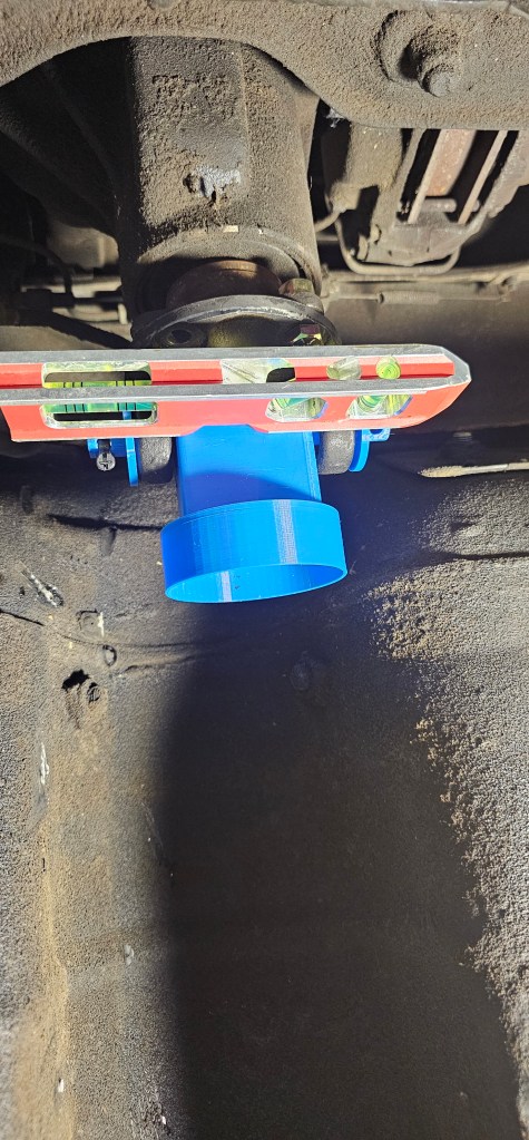
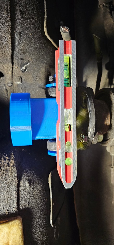
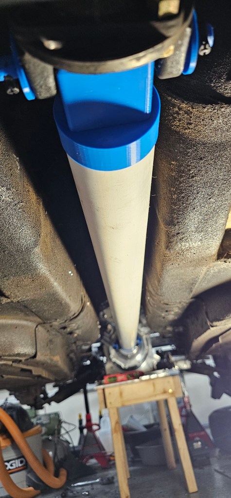
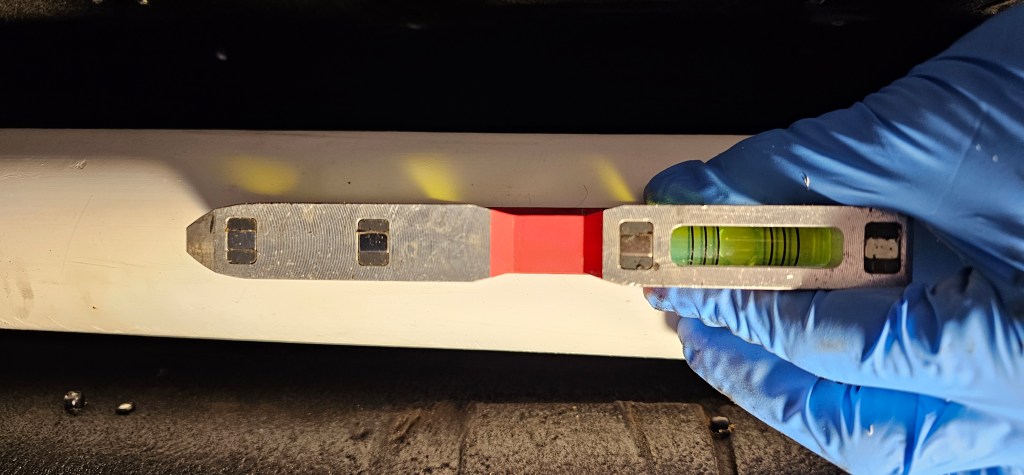
Over the last few days I made a temporary PVC driveshaft that fit into place perfectly. The angle of the diff and the motor are at zero degrees. The motor is offset slightly from center which allows clearance of the driveshaft and gives the ujoints some movement so they don’t freeze up.
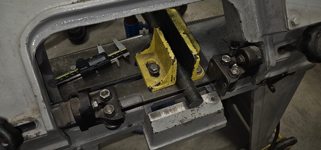
It’s time to make some mounts for the motor. The intent here is to make mounts that will eventually BECOME the final mounts. Keep in mind there are no reinforcements added yet and the aluminum frame is only for fitment.
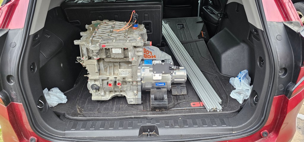
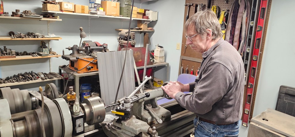
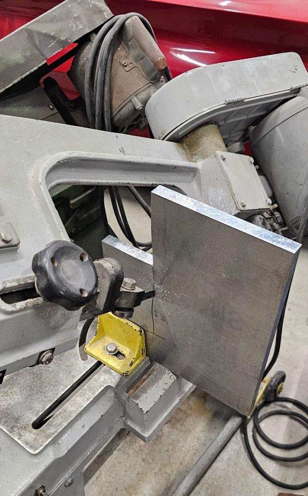
The motor is loaded up in the car and ready to take to my dad’s shop to make some mounts.
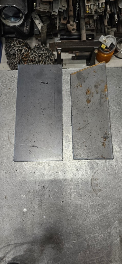
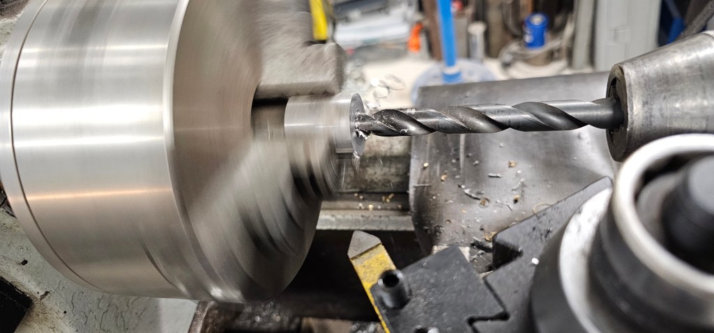
Basic shapes plasma cut and ready for machining.
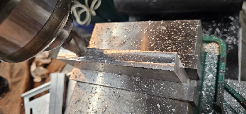
Lots of machining and dad gave me a hand making pieces!
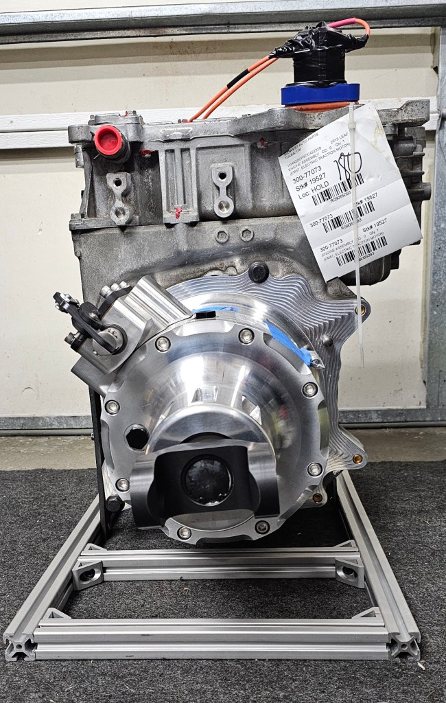
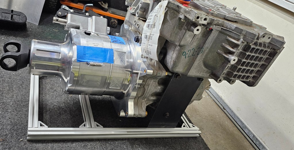
Mounted to a temporary extruded aluminum frame.
Just a ROUGH fitment in the car, but it looks like it’s going to be amazing!
Making mounts to fit is going to be a challenge, but no problem!
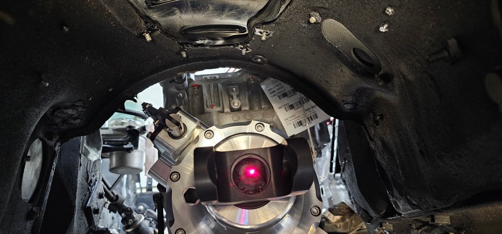
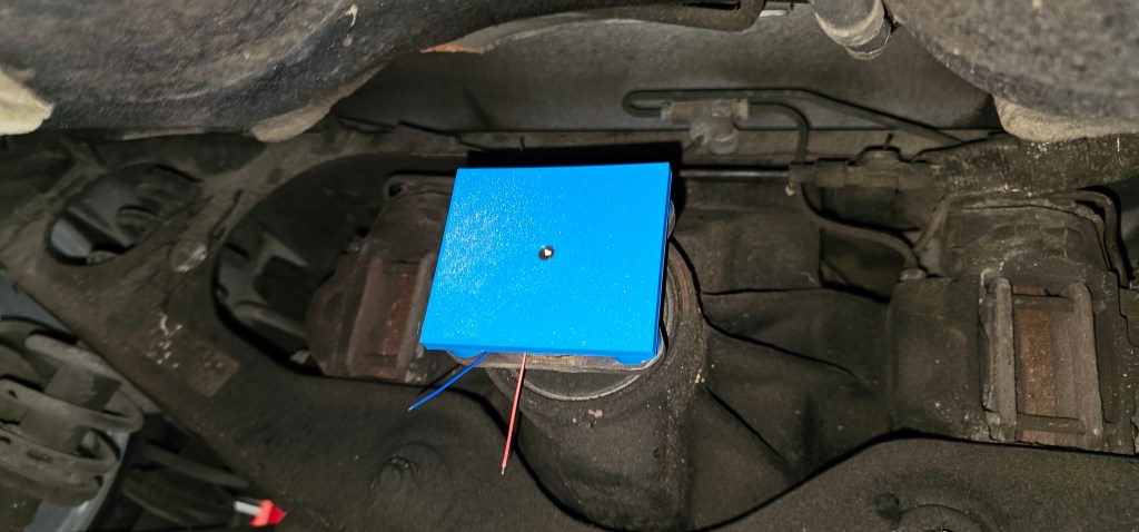
I decided that before I do anything else on this project, I need to get the motor mounted. To start, I need to see where the rear differential lines up with the front of the car. My idea is to use a laser mounted to a piece that snaps into the yoke of the rear diff, but this version proved that the laser did not shoot out straight.
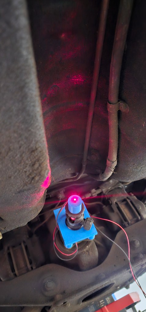
So, on to revision two that used a ball and socket mount for my GoPro. This allowed me to align the laser to a target while turning the rear diff.
Once mounted, it wasn’t too hard to get things somewhat centered.
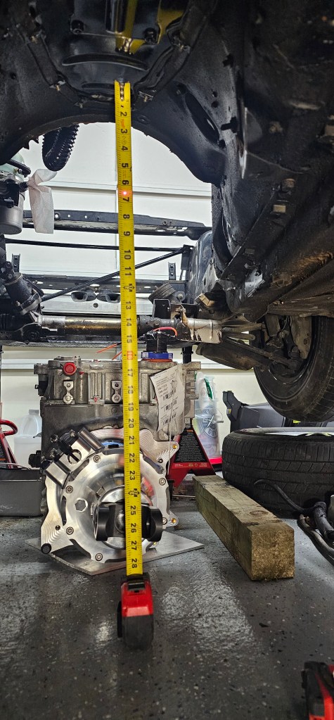
I slid the motor and TorqueBox under the car and measured about where the center of the yoke is and the laser dot from the rear diff. It looks like I can tuck this motor up tight under the transmission tunnel. It’ll be an interesting motor cradle when I’m done, but as long as it handles the torque, I’ll be happy.
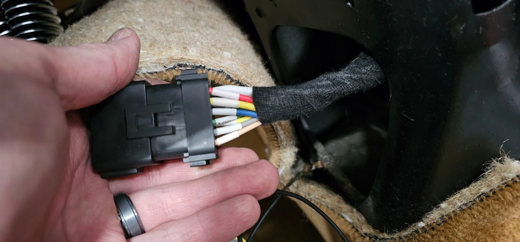
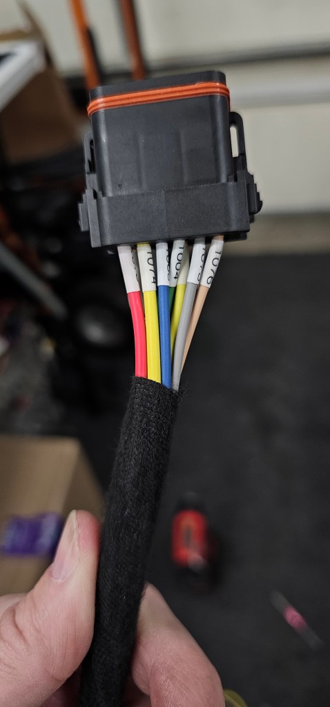
Hi! I have some time off work and a little free time, so back at the Jag project. Over the last week I’ve been able to get the passenger side door card back together, the door rewired and buttoned up.
Now the next task before I do anything else is to see where the motor is going to mount. I need to get that in the proper location before I really do anything else.
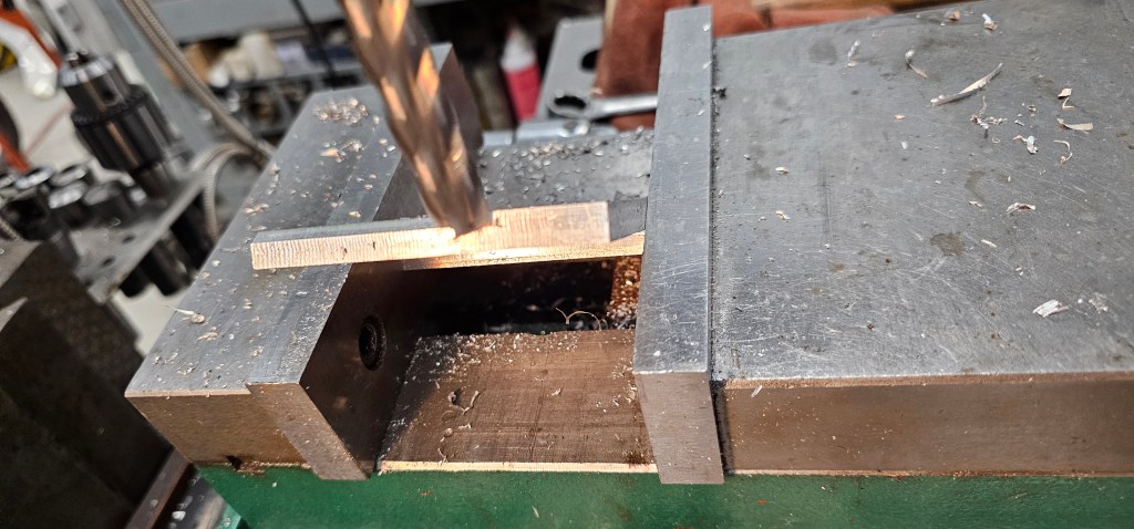
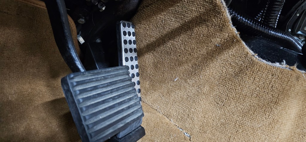
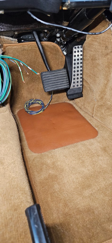
I had a few moments to work on the car recently and installed an accelerator pedal from a random Mercedes. I think they use these in a lot of vehicles, but this was one of a few pedals I found where the pivot was at the bottom and not the top. I have VERY little room in the pedal box for a different pedal and I didn’t like the cable-driven setup I had started.
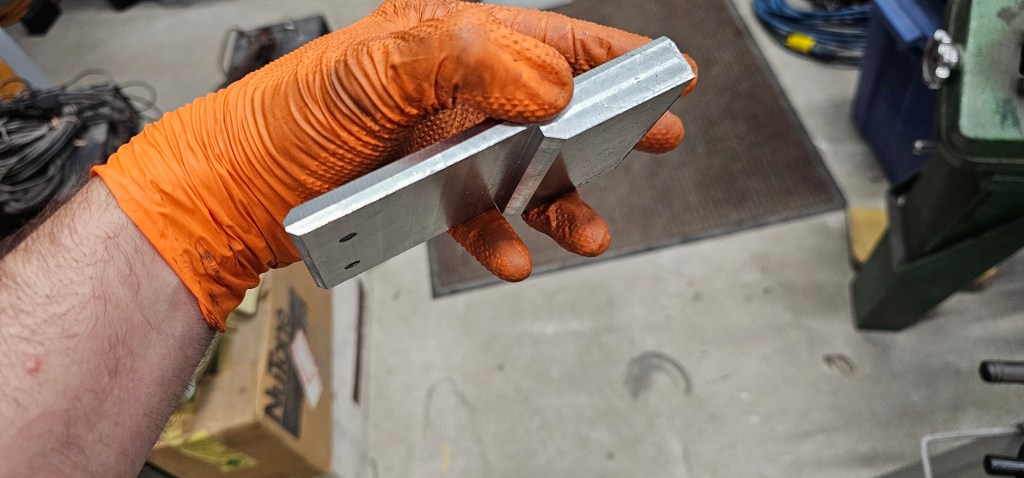
I ended up machining out a block of aluminum to hold the pedal at the right depth/angle and mounted it to the side of the transmission tunnel.
I like this pedal because it also has a double wiper, which I can use in my Thunderstruck VCU. It appears that the linearity of each pot is a little different, which may be interesting to configure.