My holiday break officially comes to a close, but I made a LOT of progress. Hopefully I’ll have some time over the next few months to get this motor buttoned down.
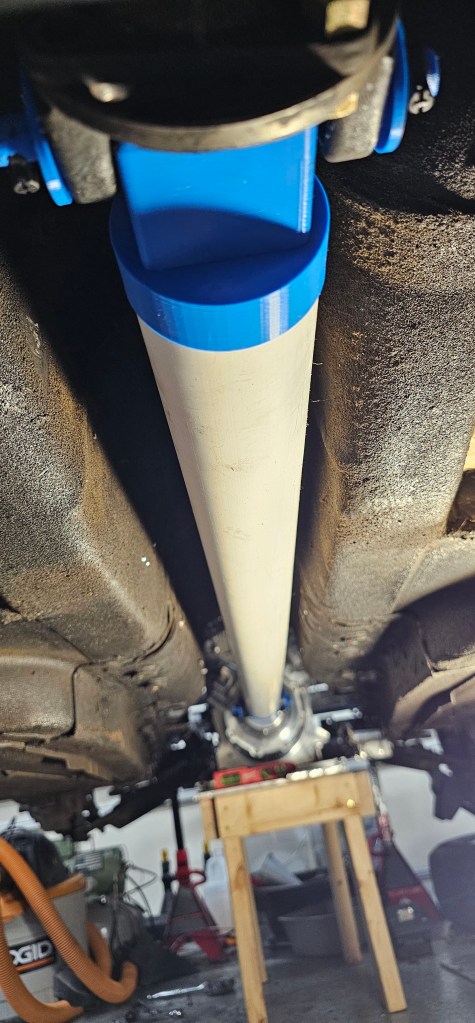
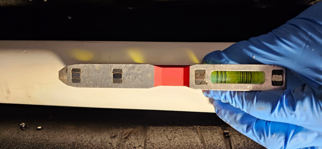
Over the last few days I made a temporary PVC driveshaft that fit into place perfectly. The angle of the diff and the motor are at zero degrees. The motor is offset slightly from center which allows clearance of the driveshaft and gives the ujoints some movement so they don’t freeze up.
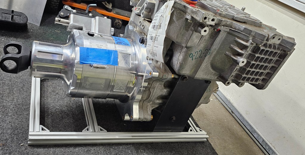
It’s time to make some mounts for the motor. The intent here is to make mounts that will eventually BECOME the final mounts. Keep in mind there are no reinforcements added yet and the aluminum frame is only for fitment.
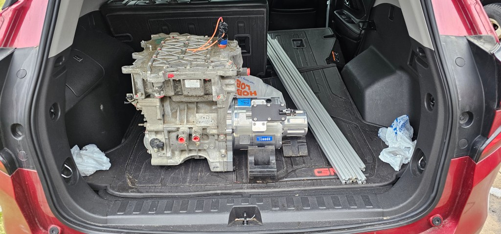
The motor is loaded up in the car and ready to take to my dad’s shop to make some mounts.
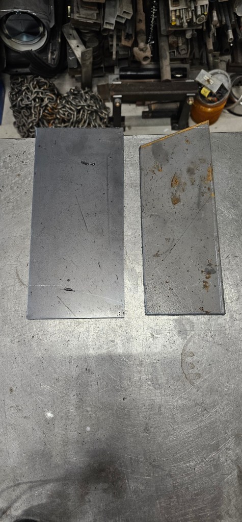
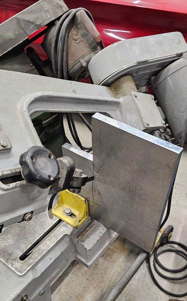
Basic shapes plasma cut and ready for machining.
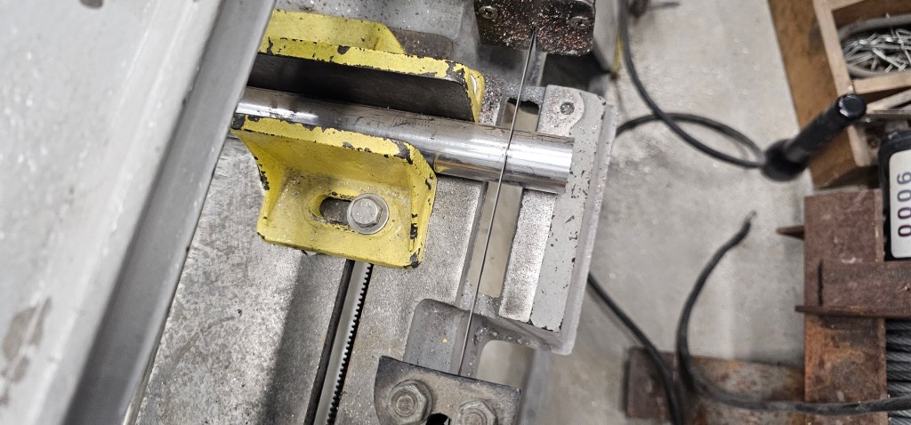
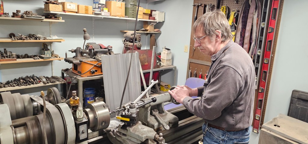
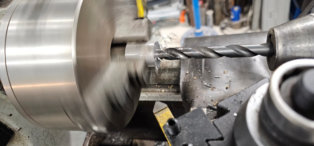
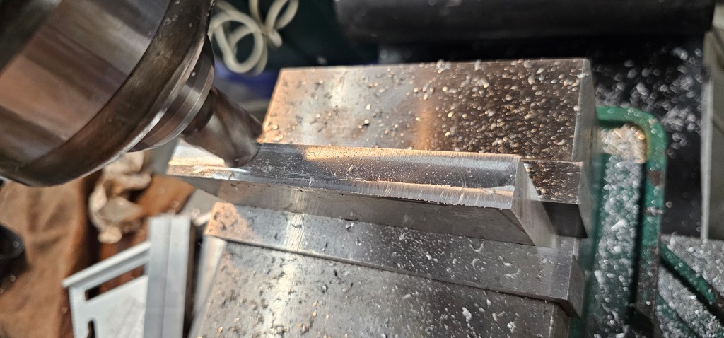
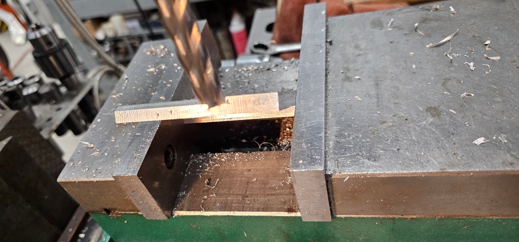
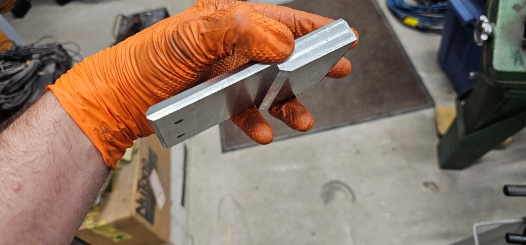
Lots of machining and dad gave me a hand making pieces!
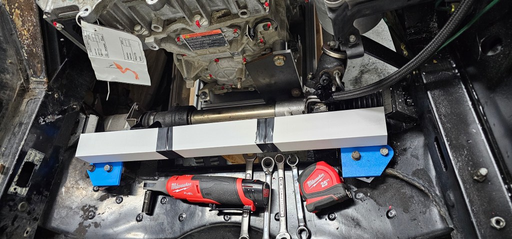
Mounted to a temporary extruded aluminum frame.
Just a ROUGH fitment in the car, but it looks like it’s going to be amazing!
Making mounts to fit is going to be a challenge, but no problem!
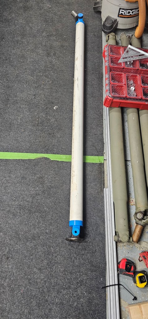
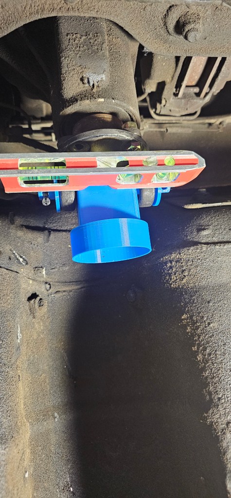
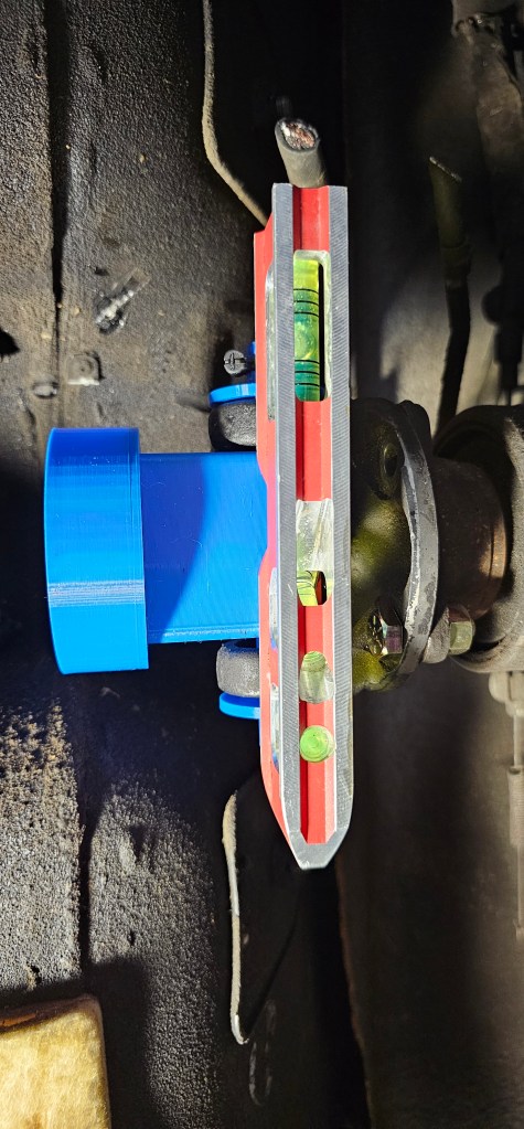
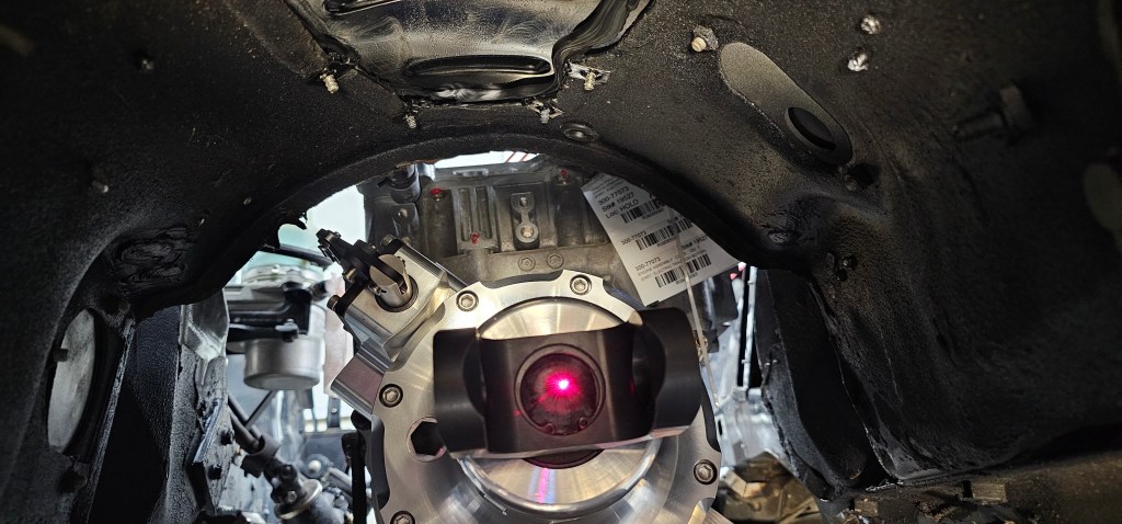
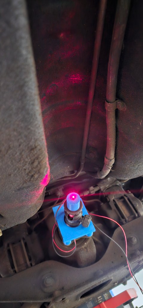
I decided that before I do anything else on this project, I need to get the motor mounted. To start, I need to see where the rear differential lines up with the front of the car. My idea is to use a laser mounted to a piece that snaps into the yoke of the rear diff, but this version proved that the laser did not shoot out straight.
So, on to revision two that used a ball and socket mount for my GoPro. This allowed me to align the laser to a target while turning the rear diff.
Once mounted, it wasn’t too hard to get things somewhat centered.
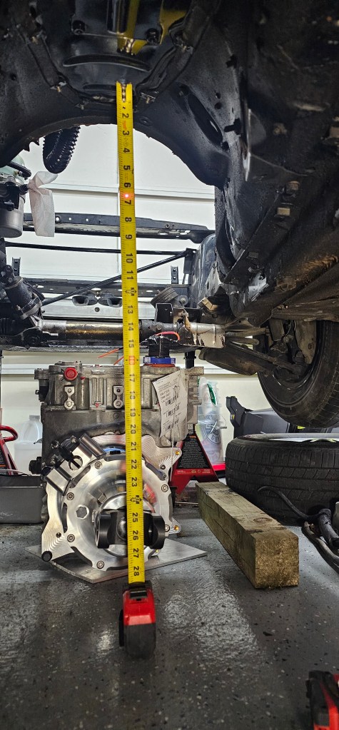
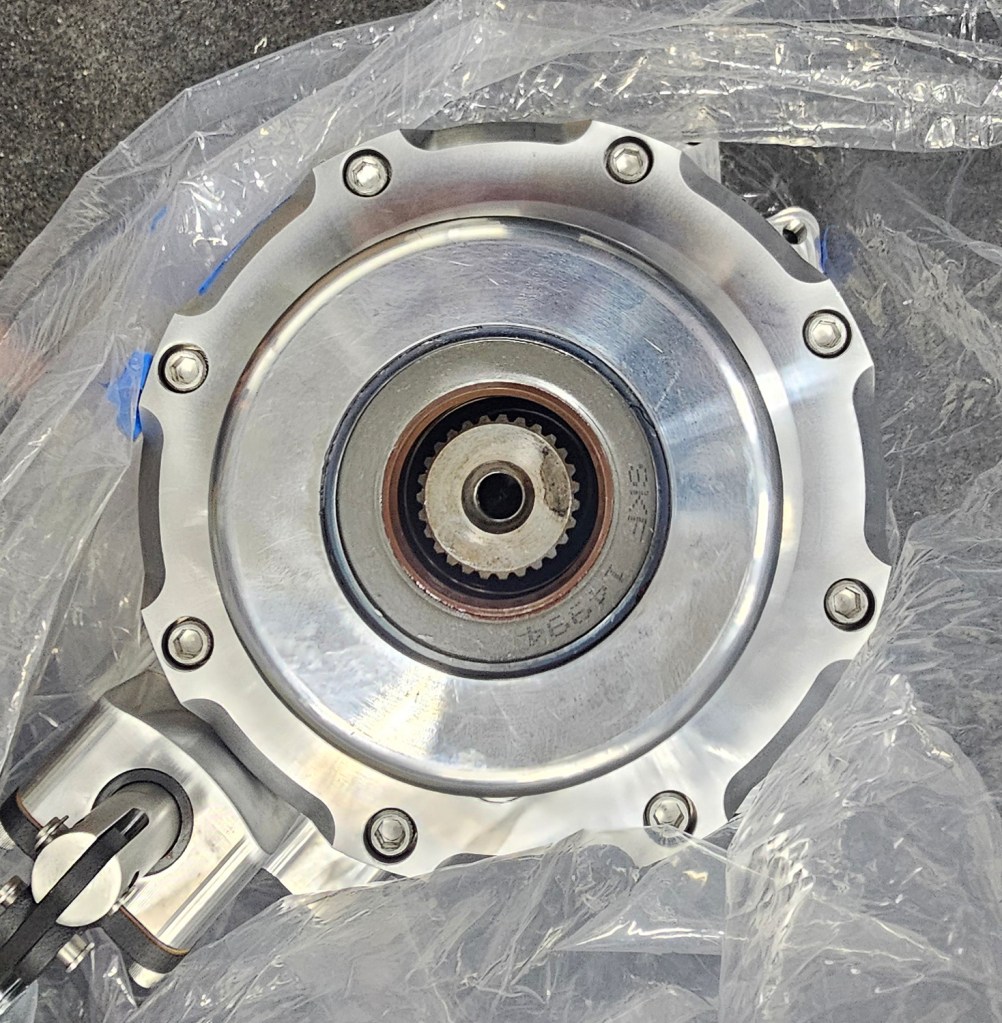
I slid the motor and TorqueBox under the car and measured about where the center of the yoke is and the laser dot from the rear diff. It looks like I can tuck this motor up tight under the transmission tunnel. It’ll be an interesting motor cradle when I’m done, but as long as it handles the torque, I’ll be happy.
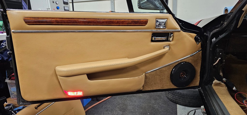
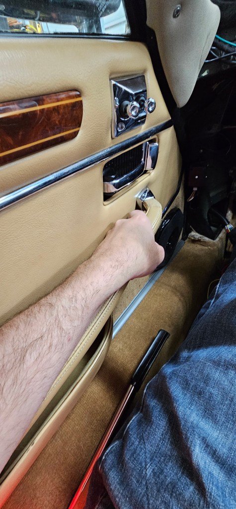
Hi! I have some time off work and a little free time, so back at the Jag project. Over the last week I’ve been able to get the passenger side door card back together, the door rewired and buttoned up.
Now the next task before I do anything else is to see where the motor is going to mount. I need to get that in the proper location before I really do anything else.
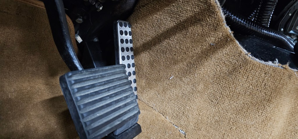
I had a few moments to work on the car recently and installed an accelerator pedal from a random Mercedes. I think they use these in a lot of vehicles, but this was one of a few pedals I found where the pivot was at the bottom and not the top. I have VERY little room in the pedal box for a different pedal and I didn’t like the cable-driven setup I had started.
I ended up machining out a block of aluminum to hold the pedal at the right depth/angle and mounted it to the side of the transmission tunnel.
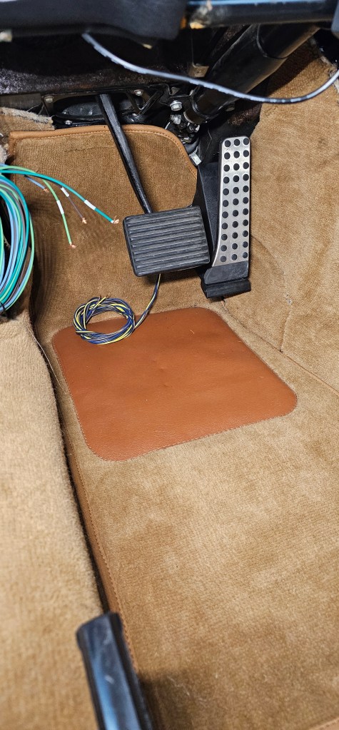
I like this pedal because it also has a double wiper, which I can use in my Thunderstruck VCU. It appears that the linearity of each pot is a little different, which may be interesting to configure.
Another month has passed and some small progress on the XJS.
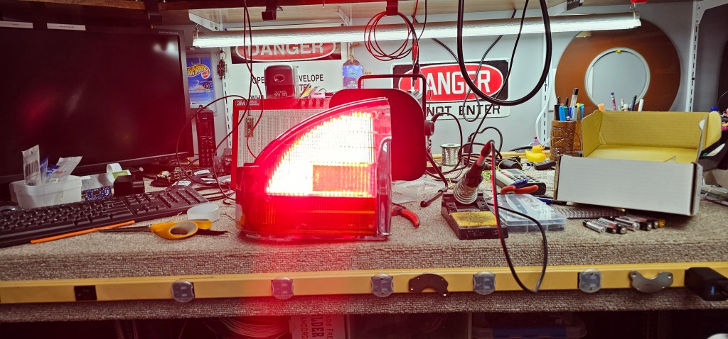
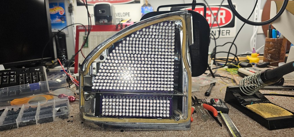
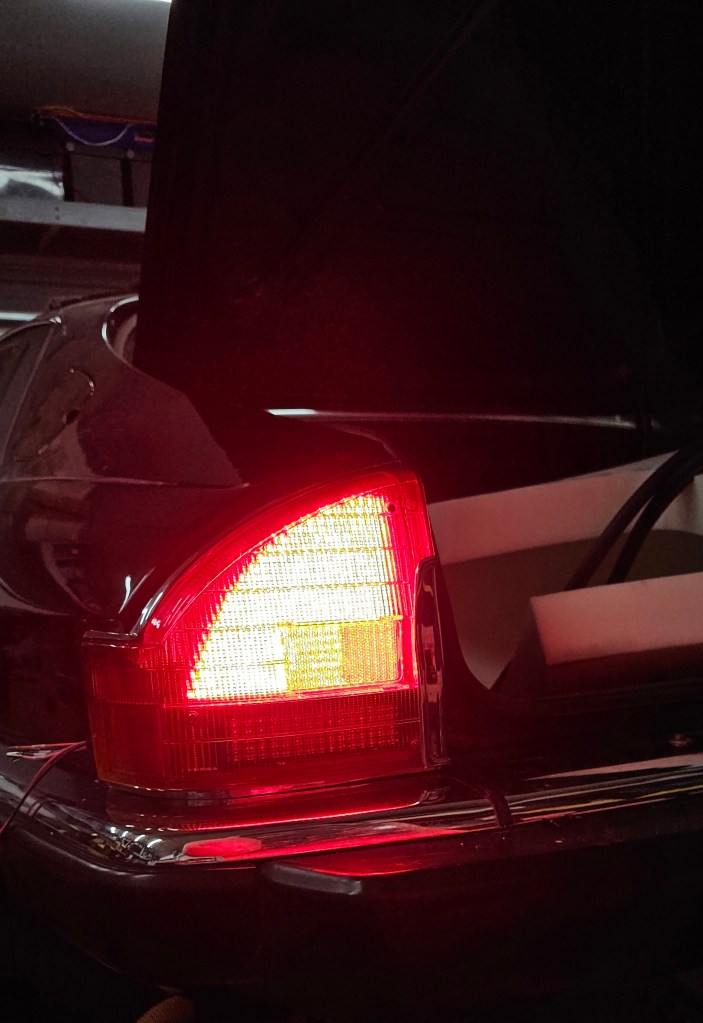
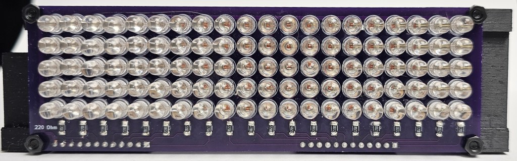
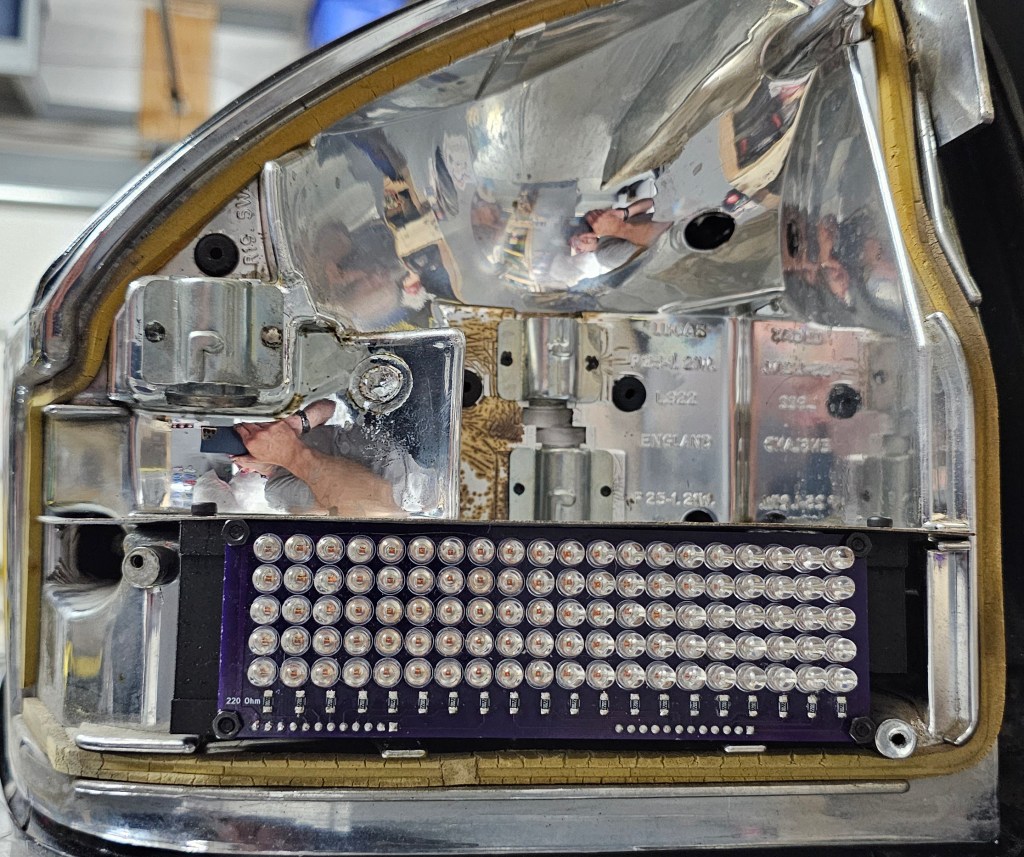
First, I have the left taillight complete! I finished the LEDs for the brake part and in total each light assembly will have 460 LEDs.
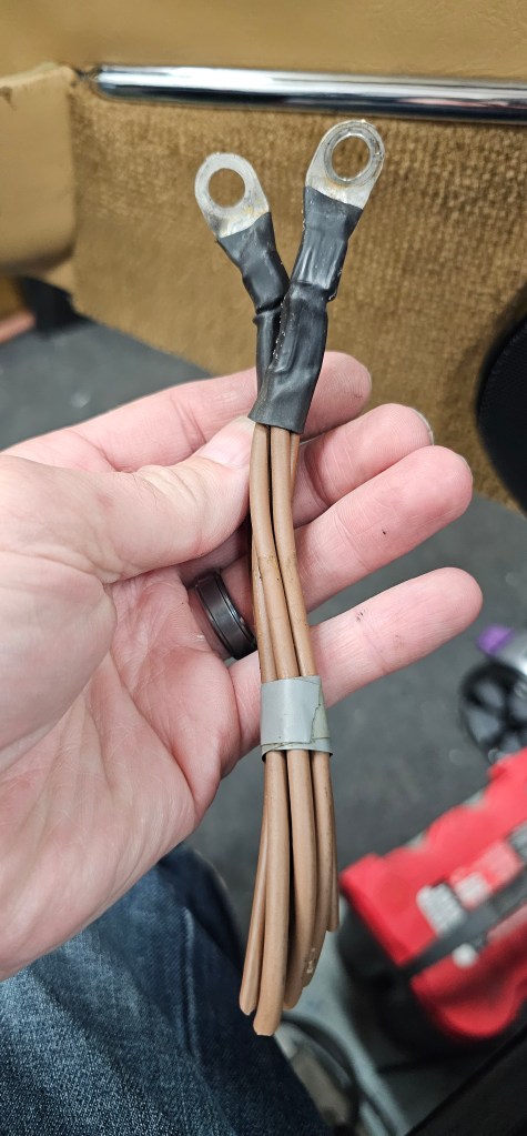
And just when you think I couldn’t find more of the old car wiring, I present this:
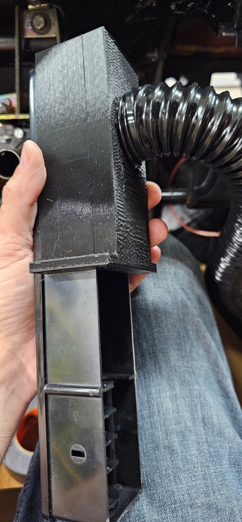
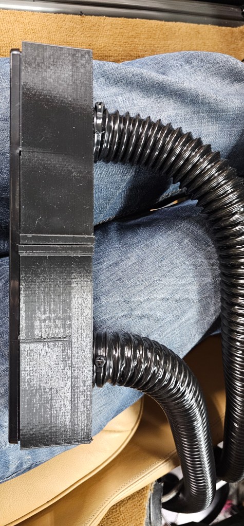
Because the HVAC is going to be all changed, I 3D printed some manifolds for all the vents to route to traditional tubing. This will eventually route under hood as that is where I am going to install the new HVAC box. A little unconventional, but space under the dash is at a premium and the setup I am looking to use will not fit.
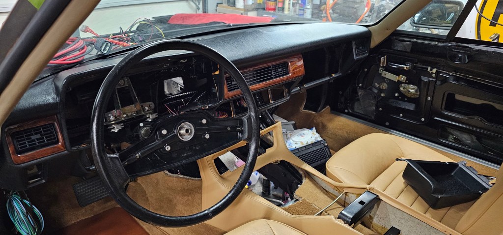
Lastly I have the dash frame and the dash pad installed and starting installing the wood trim around the bits I have complete! It’s slowly starting to look like a car again!
First, I got my wood back from British Auto Wood. Absolutely amazing job and good price. I would completely recommend! Now I’m able to put the driver door card back on!
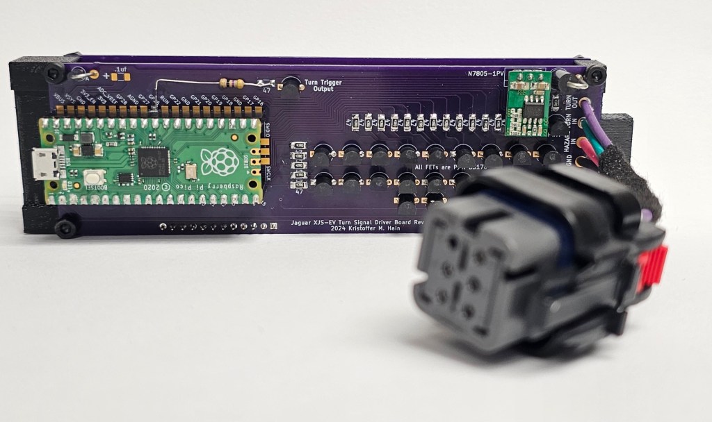
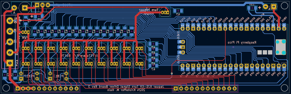
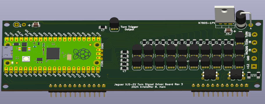
Next, I got back to finishing up the turn signal PCBs and have the driver side completed!
Here is a video of the turn signal in action. The shutter rate of the camera makes the effect look different than in person:
And when the 4-way hazards are on:
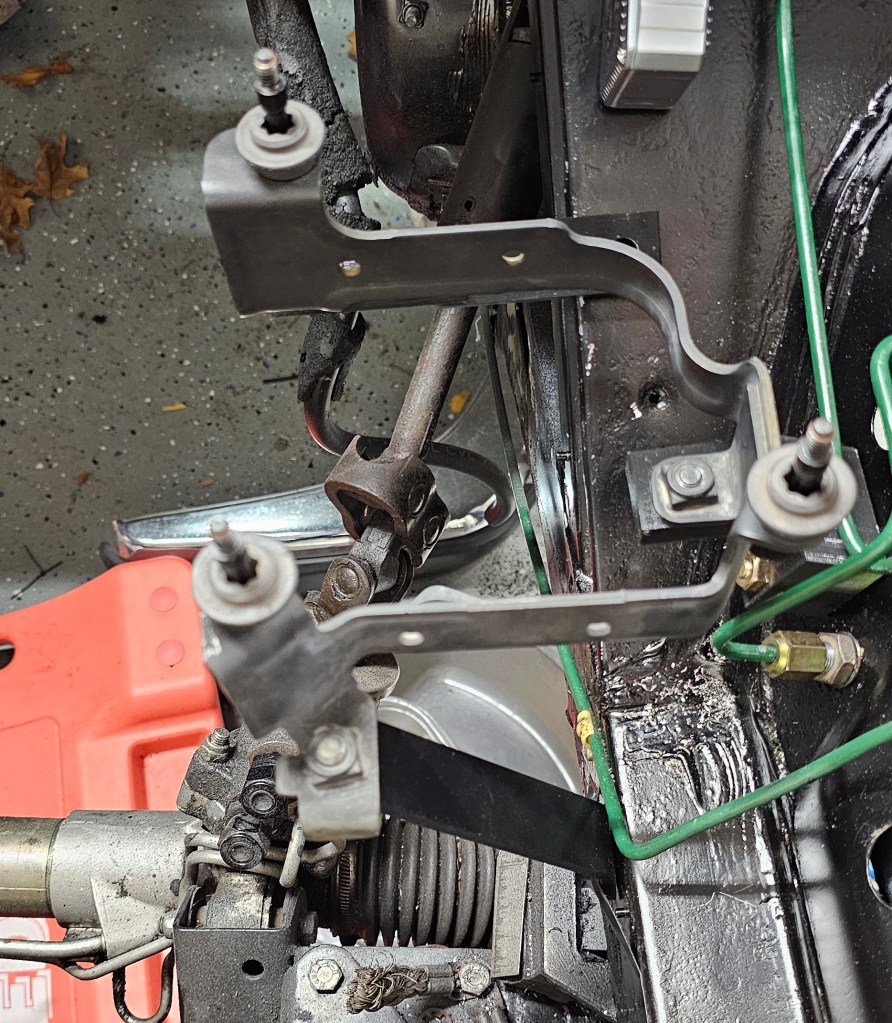
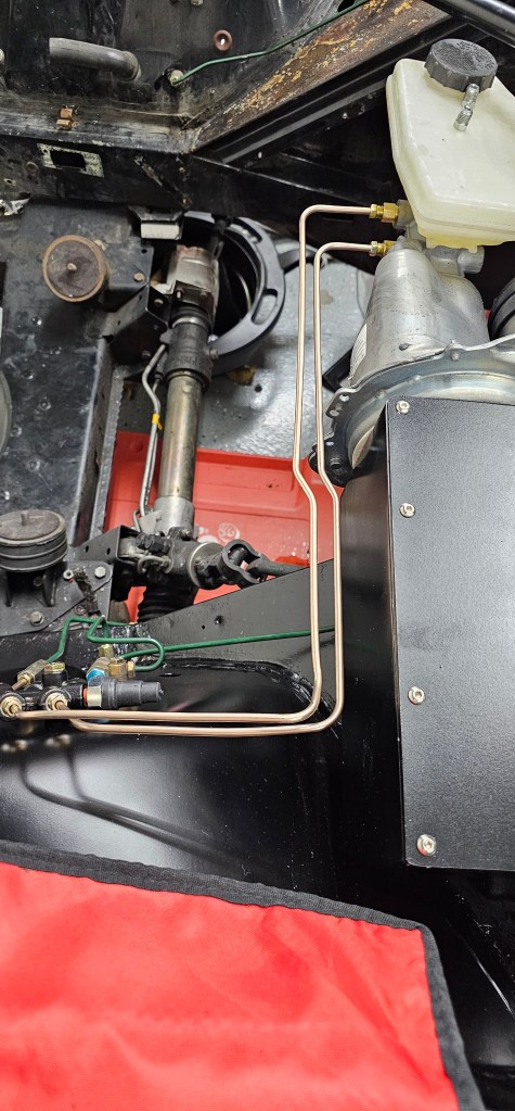
Finally I have the power steering pump installed and temporarily plumbed while I work out the CAN messages to control the speed:
Ok, it’s been a month+ since I last posted, but I have been busy and haven’t had a chance to do much with the car.
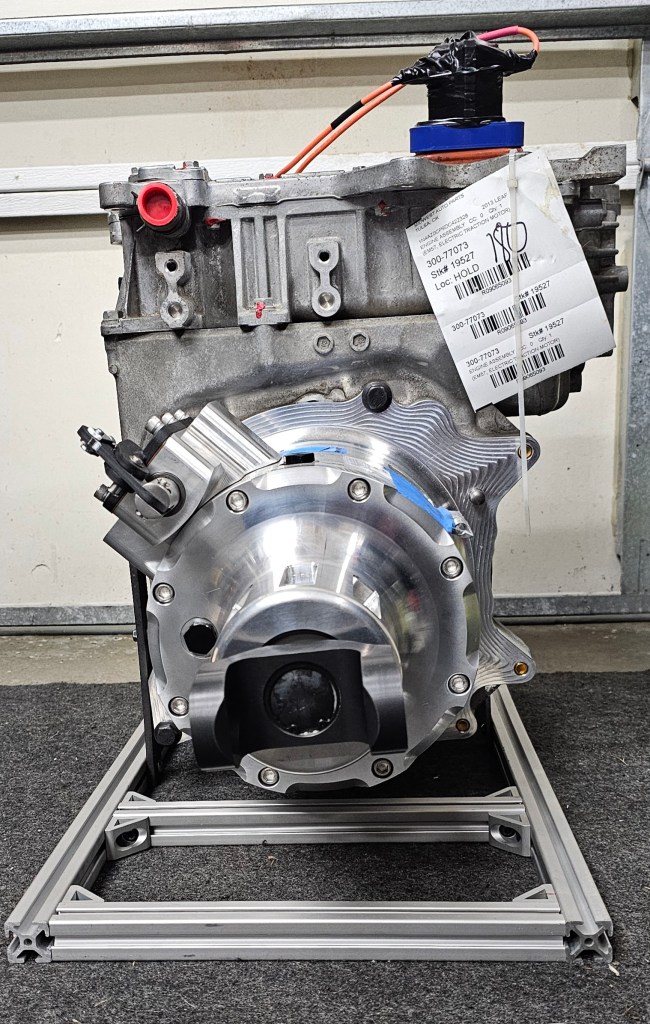
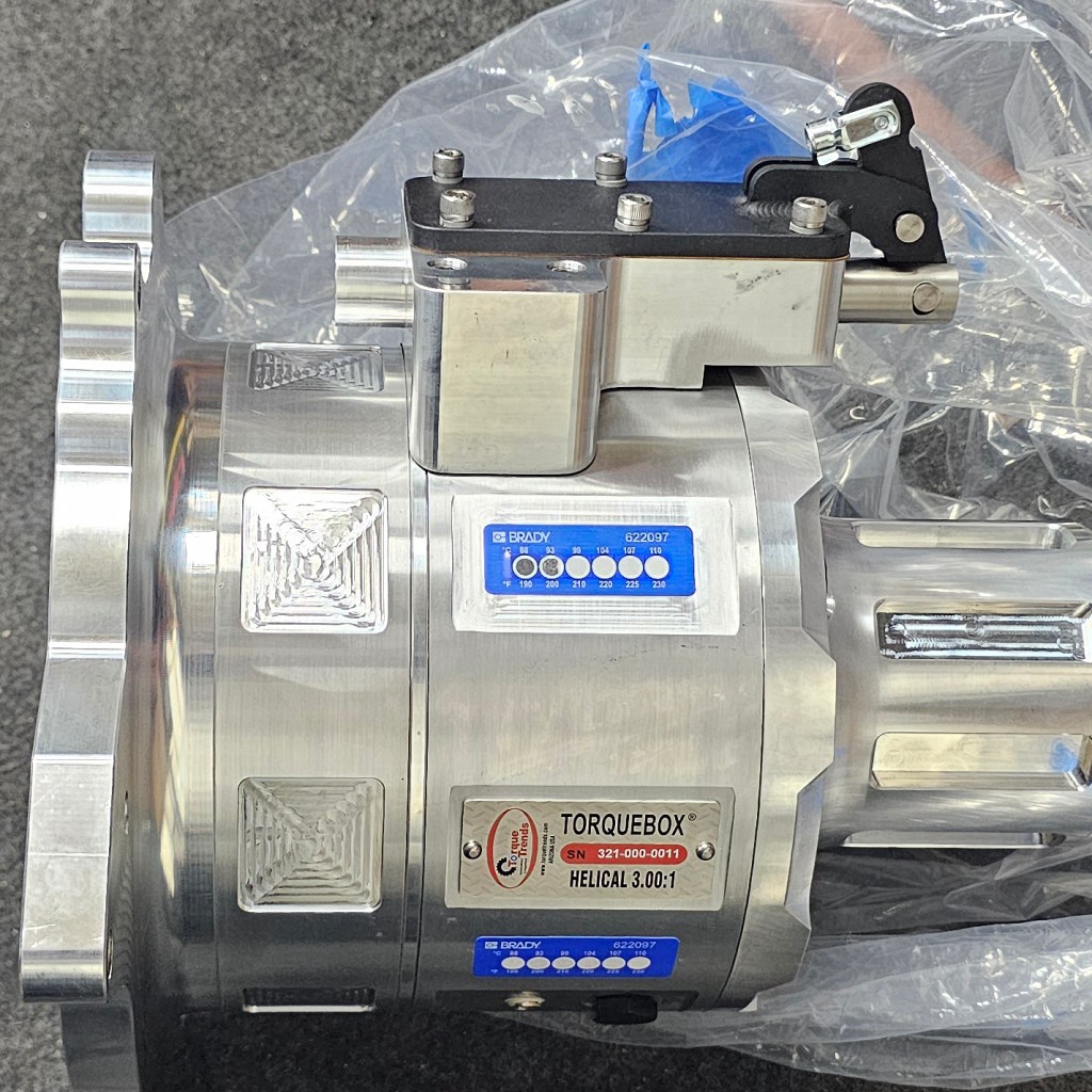
One exciting thing though is that the Torque Trends TorqueBox 3:1 reduction box is here and it is beautiful!
I also start designing brackets for the Volvo-based power steering pump. I really wanted to put an electric motor-based rack assist off a Kia, but it just won’t fit with how tight things are both under the dash and to the rack, so this is the next best thing. Making the brackets out of 3d prints first to make sure everything fits up, then will make them out of metal.
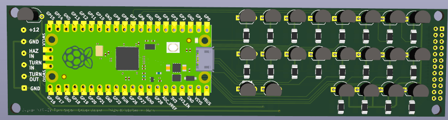
Lastly I’m working on revision 4 of the turn signal controller board. Rev. 1-3 did not work out so well. Hopeful I have it right this time!
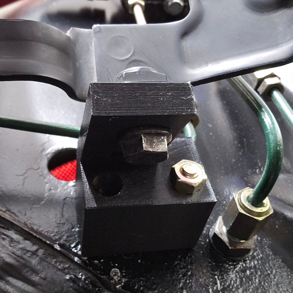
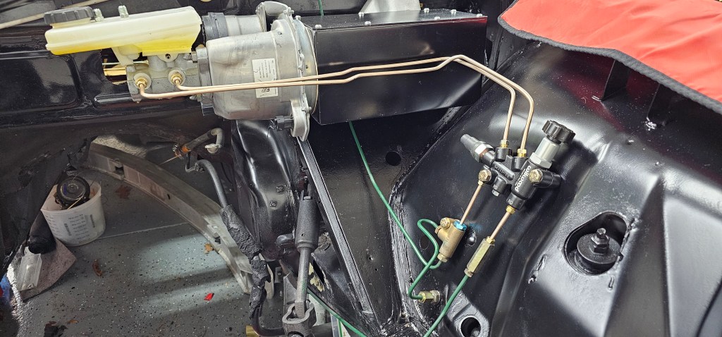
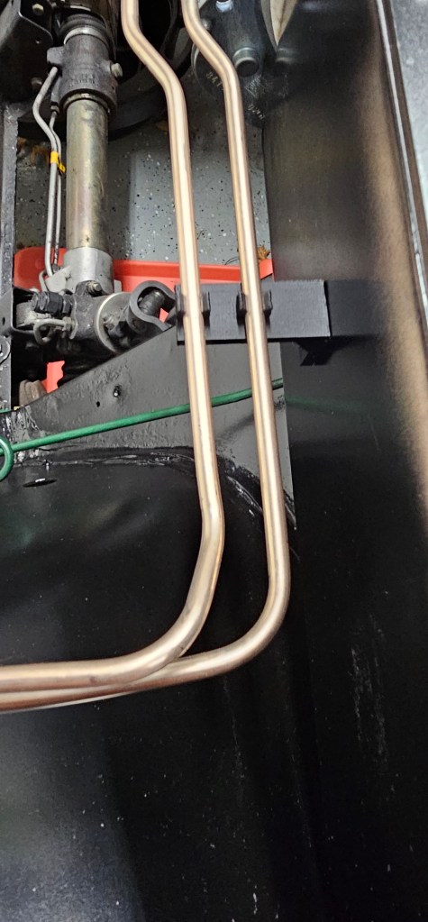
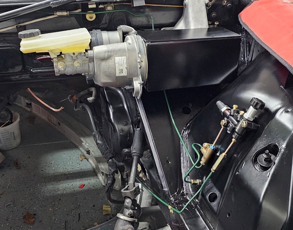
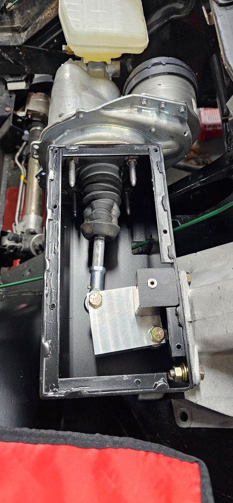
This weekend I bolted the brake booster in for what I hope is the last time. I made a gasket for the lid and did my best at bending the nickel-copper lines. I then designed and 3d printed a small clip to hold the lines in place. It didn’t turn out too bad!
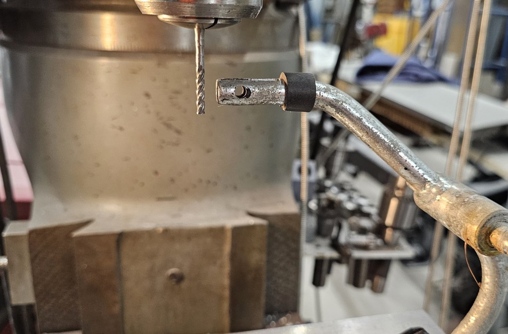
I started working on the throttle for the vehicle. Using the existing pedal because no modern electronic pedal will fit, but rather than using all the linkage over (that was used for the transmission kickdown and cruise control) I am running the cable right to the pedal. The issue is that the gap in the pedal had to be widened about .020″ – – which meant I had to do this sketchy thing:
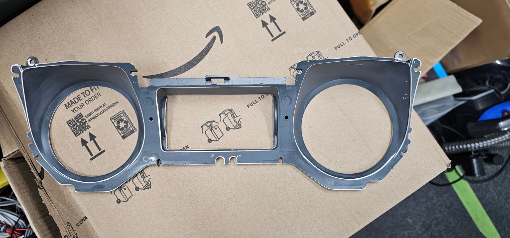
Aside from all that I also cleaned up the instrument cluster mid plate and primed it. Hope the right color paint arrives this week and I can get the cluster going again!
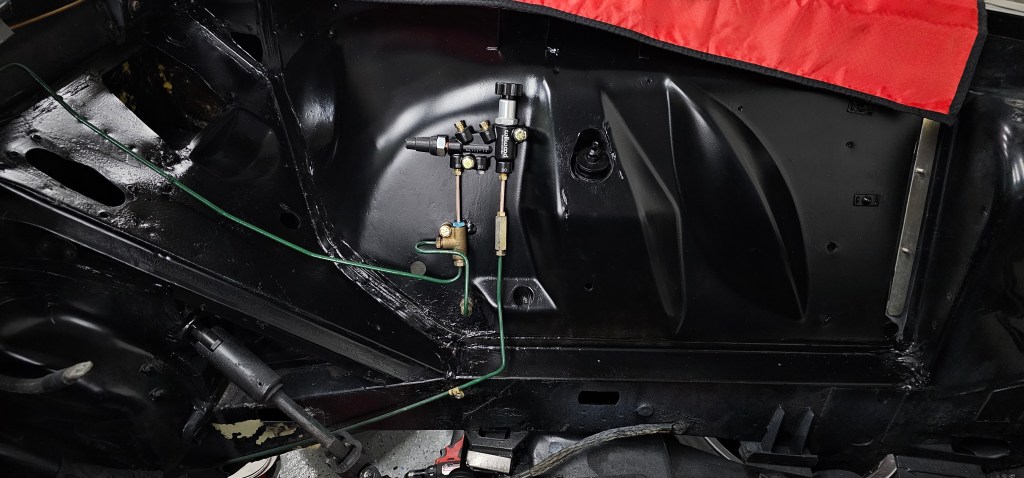
I’ve been sick most of this weekend so I haven’t done much here. However, I have the brake box completely painted and assembled for (hopefully) the last time. I need to make a new throttle ingress plate first before I bolt this to the car, but I’m close. I also mounted the brake proportioning valve and plumbed that in.
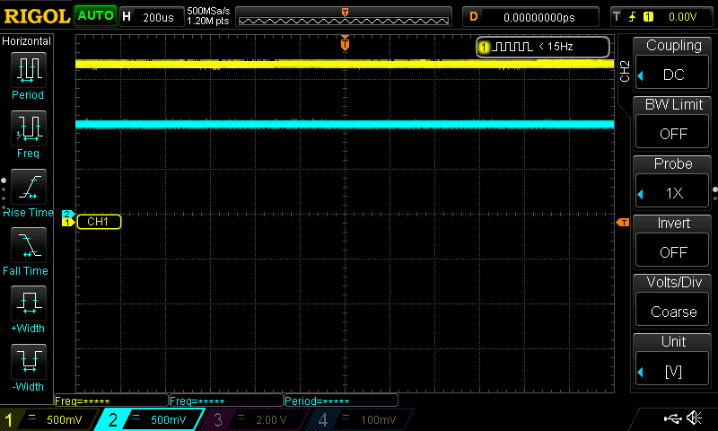
It’s been close to two years since I started the taillight portion of the project, but I finally drew up the PCB for the taillight controller. I have sent this out to Oshpark to make a board and hopefully no mistakes!